Subscribe Button 1
SUBSCRIBE

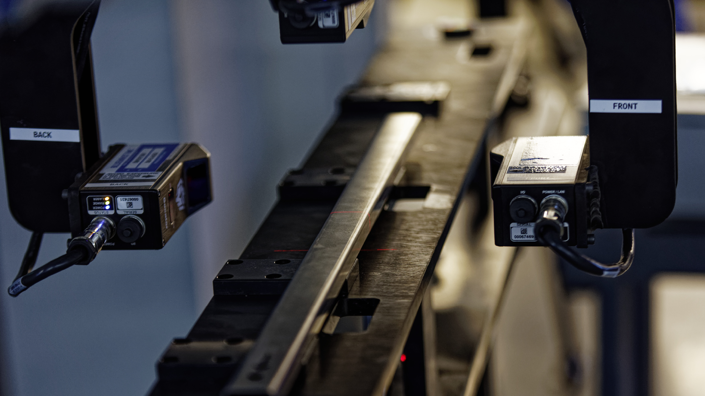
Robotics 3D Vision Toolbox Simplifies 100% Inline Metrology-Grade 3D Inspection

Long structural objects such as rails or support beams are often foundational building blocks for much larger and complex products such as vehicles, ships, trains, or building support components. As the main support platform for many additional add-on components, these structural items are fabricated with many different types of holes, slots, and mounting points that must be in precise geometrical locations based on GD&T specifications. In addition, all physical sides of the structure must conform to strict dimensional tolerances without warping to ensure the final assembled products will conform to design specifications and performance metrics.

Traditional Inspection Methods are Slow, Error-Prone, and Can Pass Defects Downstream

Due to the large physical size of such structural items, inspection is usually carried out manually by quality-control personnel taking physical measurements of the critical features using a CMM or gauge fixtures. While both methods offer metrology-grade accuracy, they are slow and can be only done on a sampling basis; as a result, manufacturers risk passing on defective parts downstream. Typically, 100% inline inspection and full traceability are lacking, as manual quality control relies on pass-or-fail metrics.

These methods are also time-consuming and error-prone due to operator subjectivity or other human factors. It also requires parts to be removed from the production line and moved to a separate inspection area, which may further impact the plant throughput. Expensive fixturing is also needed to secure the part on the inspection station to ensure the measurement result is repeatable and accurate. This type of inspection provides only partial coverage of the part and incomplete dimensional information such as the presence of warping or the geometrical relationship of the features to one another.

Breakthrough with Multiple 3D Mounted Cameras for 100% Inline Metrology-Grade Inspection

To overcome this limitation, multiple 3D line profile scanners can be mounted on a linear slide to provide complete coverage and inspection of the part in one single pass. While this solution sounds good in theory, in real life it introduces a host of complexity and errors which, if left unchecked, will result in an unusable system.

A long (2M +) linear slide is not always a perfectly straight line and may contain minute deviations invisible to the naked eye. Parallelism between the reference edges of the rail and the block plays a large part in determining the travel accuracy of the mounted 3D camera. Longer linear slides also introduce system inaccuracies caused by yaw, roll, and pitch as the camera travels on the rail, which will affect the final scan quality of the part. These deviations will affect the accuracy of the 3D camera and the quality of the point cloud, rendering it useable from a quality-control standpoint due to lack of accuracy and point-cloud deformation.

There is also the technical challenge of stitching the 3D scan data from multiple cameras together to present the physical part in 3D space for accurate comparisons against CAD or GD&T specifications. When you use more than one 3D camera on a linear slide to cover multiple surfaces, errors are compounded, making the whole system unusable without special calibration and error compensation techniques. Lastly, temperature fluctuations will introduce additional errors to the system caused by the mechanical expansion and contraction of the fixture and linear slide.

Without a specialized software solution or a robust methodology, such a setup often requires trial and error that consumes a large amount of valuable engineering time that ultimately results in project failure. This is the reason why very few implementations exist in the field and the final inspection process becomes a production bottleneck that will affect the overall productivity of the plant.

Overcoming Limitations & Breaking Barriers with Robotics 3D Vision Toolbox

Unblink3D has decades of experience in developing custom 3D vision solutions used by major automotive OEMs and Tier-1 manufacturers for the most critical 3D vision quality-control inspection tasks. The company developed its Robotics 3D Vision Toolbox to help manufacturers compensate for up to 99.9% of all errors encountered with a linear slide-mounted 3D vision inspection application, while delivering a spatial error of 0.1mm compared to nominal.

The toolbox has a linear slide calibration feature that allows a baseline measurement of the fixture accuracy and helps determine the angle between the sensor and direction of the linear slide. Using a custom-designed thermally stable scan artefact placed along the linear slide scan path, combined with Unblink3D’s proprietary algorithm, users can achieve high quality, error-free metrology-grade inspection accuracy. Unblink3D’s inspection solution gives customers complete dimensional measurement information for all critical features. It also checks for deformation, which is not possible with a 2D solution.

Simplified Design & Deployment with 3D Laser Scanner Visualization Tool

To help users save on engineering time and trial and error measurement, the Unblink3D Robotics 3D Vision Toolbox features a cloud-based sensor visualization tool that simplifies project design using multiple 3D cameras. With this tool, users can virtually build out their project in 3D space, perform feasibility studies using the sensor resolution checker and relative transformation calculator. Preloaded with a large database of popular 3D camera specifications such as resolution, FOV, and housing size, the visualization toolbox makes system design and verification possible before the physical implementation is built.

To date, several customers have successfully used the toolbox and implemented several tri-sensor 3D inspection solutions to check parts such as structural support beams and vehicle seat rails.

For more information: www.unblink3d.com


HOME PAGE LINK