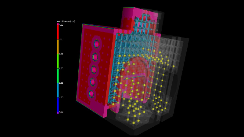
Volume Graphics Releases Version 3.4.5
Volume Graphics has released version 3.4.5 of VGSTUDIO MAX, VGSTUDIO, VGMETROLOGY, VGinLINE, and myVGL.
New features and capabilities in the latest release include:
Users can inspect cast parts for porosity according to the BDG Reference Sheet P 203 and perform a 3D evaluation with regard to the most critical defect parameters within functional areas of the part. The new P203 analysis within its Extended Porosity/Inclusion Analysis Module allows users to generate porosity keys using an intuitive interface, define a reference volume exactly according to the inspection plan using the ROI functions of VGSTUDIO MAX, providing a quick overview of all global tolerancing criteria and results for the P 203 analysis. The new P203 analysis includes porosity tolerance per region, equivalent defect diameter, and the total number of defects as tolerancing parameters.
The new P203 analysis within the Extended Porosity/Inclusion Analysis Module includes defect evaluation and independent tolerancing of different ROIs within one P 203 analysis, the ability to more flexibly combine the tolerancing and filtering of defects based on their characteristics, and the option to evaluate freeform reference volumes (ROIs) only inside the object’s boundaries (surface), which makes it easy to set up a fully automated in-line inspection. To efficiently and flexibly inspect a part, the P 203 analysis function is equipped with additional features such as porosity and hot spot calculation, distance to machined surface, annotations, and bookmark image generation. Like VGEasyPore, P 203 offers new subvoxel accuracy and absolute and relative defect contrast definition.
With the added support for BDG Reference Sheet P 203, VGSTUDIO MAX together with Q-DAS qs-STAT cover the complete loop from the specification of porosity tolerancing criteria according to P203 by the product designer to statistical process control by the quality engineer. Now, it’s possible to easily transfer tolerancing criteria for porosities from drawings to the software without errors. The tolerancing keys in the drawing are displayed in the software and an overview of the corresponding tolerancing results is displayed in one easy-to-understand table. The results of a P 203 analysis can be exported to the Q-DAS software qs-STAT for statistical process control.
The latest release of VGMETROLOGY v 3.4 capabilities include:
Users can now easily create a surface mesh that compensates for the difference between the actual object and a reference object directly from the Manufacturing Geometry Correction module saving time by reducing the number of iterations as opposed to a trial-and-error approach for the final printing geometry optimization. Compensate of the mesh sent to a 3D printer to eliminate deviations in the nominal geometry caused by distortions. Such distortions are inherent in the 3D printing process and may even remain after a previous optimization based on a 3D printing simulation.

Users can now indicate numerical deviations at certain positions on the surface in addition to visualizing the tolerance deviations via color overlays by creating annotations for geometric tolerances. The annotations are shown in the Scene Tree as well as in the new reportable annotation table in the ‘CM reporting’ dialog. The ‘Features’ tab in the coordinate measurement reporting is also expanded by an additional annotation table, which shows the annotations for the currently selected feature. Annotations can be created either manually at the desired positions in the views or by pasting pre-defined positions from the clipboard into the annotation table of a certain feature. The annotations can also be pasted between different geometric tolerances and are part of coordinate measurement and evaluation templates.
Exporting measurement results to Q-DAS software qs-STAT for statistical process control now includes associated images that indicate the position of the measured features on the part. These images can then be used to set up a report view in qs-STAT, which will be populated with the results of many measured parts. Visualizing measurement time series and the position of the measured features on the part make it easier to evaluate results, for example to locate a potential need for an injection molding tool correction during machine qualification or while production is running.

The software now creates a log file to report problems that occurred in the PMI data translation step when importing advanced CAD files. Sometimes, it is not possible to translate all measurements from PMI data into a coordinate measurement template, such as when data is incomplete or ambiguous. Often, these problems can be avoided in the originating CAD system by providing necessary semantic information for the PMI data. The log file now allows users to easily detect well-known problems by identifying problematic CAD entities and giving you tips on how to resolve these issues.
To separate thick from thin structures, users can now create a ROI from a wall thickness range. This can be very useful for when segmenting thin struts and thicker nodes in additively manufactured lattice structures or performing a porosity analysis to a specific region. Because separation by wall thickness is now only one click away, users no longer need to use manual segmentation tools to separate any structures with varying thicknesses.
You can now approach the perfect tool (mold) shape slowly without running the risk of removing too much material using the new additional manual compensation offset that’s been added to the automatically calculated tool offset. This tool helps users easily decrease or increase the tool offset derived from the nominal/actual comparison between the part CAD model and the tool CAD model.

Use the new intersection function on circle elements to easily detect the intersection point of a circle and the surface of a part, which is required for certain measurement tasks or alignments (e.g., on gears or other rotational structures). The maximum number of result points as well as their order can be specified. Moreover, the intersection points are also part of coordinate measurement templates, which allows them to be easily transformed and applied in a pattern.
Support of BDG Reference Sheet P 203: The new P 203 analysis of the Extended Porosity/Inclusion Analysis Module allows users to inspect cast parts for porosity according to the Reference Sheet P 203 of the Federation of German Foundry Industry (BDG). It also allows users to perform a 3D evaluation with regard to the most critical defect parameters in functional areas of the part. Together, VGSTUDIO MAX and Q-DAS qs-STAT now cover the complete loop, from specifying porosity tolerancing criteria according to P 203 by the product designer, to statistical process control by the quality engineer:
For more information: www.volumegraphics.com