
Non-Contact Measurement With Optical Displacement Measuring Sensors
To ensure consistent quality is achieved when manufacturing many different devices or components, the results of the production process need to be checked regularly by taking measurements. These checks are performed in various ways: either outside of the ongoing process, by regularly removing individual devices and checking them using appropriate mechanical or optical measuring instruments; or via measuring stations integrated into the process, which are equipped with mechanical sampling systems or other non-destructive measuring instruments. Optical measurement sensors are ideal for integration into the manufacturing process..
Their ability to measure precisely, quickly and without contact, plus the option to integrate the results of these measurements into the production process directly, leads to increased productivity. This results in faster production processes at a consistently high quality, without the need to make mechanical contact with the object or damage it in any way. Optical sensors provide extremely accurate results even when measuring very small objects.
Various technologies are used to create precise optical measurement sensors with the most popular being:
Laser Triangulation Principle
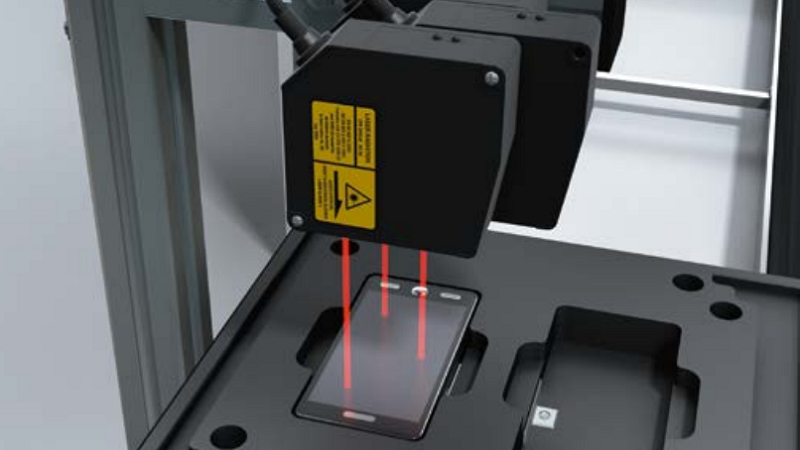
Laser triangulation is a single- or multi-dimensional distance measurement resulting from an angular calculation. The sensor projects a laser light onto the measuring object. The beam reflected there is then mapped, via optics, to a particular place on a position-sensitive receiver element, depending on the distances involved. The distance to the measuring object is determined by triangulating the light source, the measuring point on the object, and the image of the light on the receiver element. Sensors are available with light spots of different sizes. It is better to use small light spot geometries for very small objects, whereas a sensor with a larger light spot is recommended for rough surfaces.

The same principle of operation also applies to sensors which use not a light spot, but a laser line, combined with a CMOS matrix receiver. In this case, a profile can be detected and evaluated directly, without having to move the object.
Chromatic-Confocal and Interferometric Measurement Principle
 Chromatic-confocal measurement sensors use white light sources, whose light spectrum is directed to the measurement head via optical fibers. The OC Sharp displacement measurement sensor from SICK allows the user to choose from two different measuring methods.
The lens system integrated in the measurement head has been designed such that the individual wavelengths are all assigned to a different distance. OC Sharp makes use of chromatic aberration, which is usually an unwanted effect. Each wavelength is focused at a different distance, reflected by the surface, and the reflected wavelength is then evaluated in a spectrometer. The wavelength determined is assigned to a distance value in turn.
As with many sensors which operate according to the laser triangulation principle, several reflected wavelengths can be evaluated in this case too, thus enabling a relative material thickness to be determined for single- or even multi-layered transparent objects.

Interferometric Measuring Method
The interferometric measuring method uses the physical effect of interference on thin layers. We are familiar with this effect from puddles that shimmer with color, caused by a thin film of oil, or from soap bubbles, for example. Different wavelengths of the light are either weakened or strengthened by specific material thicknesses. A quick Fourier transformation is then used to evaluate the spectrum of the detected layers. Unlike with the chromatic-confocal measuring method, here it is not possible to evaluate an absolute distance, but just the thicknesses present in a system of layers.

Significant advantages over the laser triangulation principle are exhibited including:
• Larger tilt angles are usually permitted
• If the light path is partially shaded, a measurement result will still be obtained
• Light spot diameters of 4 µm enable very small areas to be measured or even allow measurements to be taken inside holes
• Even smaller layer thicknesses of transparent materials can be determined (over approximately 3 µm)
• The measurement principle for taking measurements of surface roughness has been described in a standard (DIN EN ISO 25178, Part 602)
• The measurement head is a purely passive device and contains no electrical components
Challenges
There are many reasons to use optical measuring instruments:
• As a replacement for mechanical measuring instruments, which are subject to wear and therefore have to be replaced on a regular basis
• If damage to the final product, e.g., films or soft surfaces, caused by mechanical measuring instruments is to be avoided
• If the properties of the material to be measured do not generally allow for a mechanical measurement to be taken, e.g., media which are liquid, not yet hardened or basically soft, whose dimensions would change either reversibly or irreversibly if subjected to pressure
• If the surface to be measured cannot be accessed by mechanical measuring instruments, or can only be accessed with difficulty
 When changing over to optical measuring instruments, a challenge which sometimes has to be met is how to achieve results that are comparable with those previously obtained by mechanical means.
Due to the different ways in which optical and mechanical measuring instruments work, the following must be taken into consideration:
• Is it even possible to measure the object or will the results by significantly influenced by physical factors, e.g., by semitransparent surfaces or multiple thin layers?
• How are deposits (e.g., oil, dust, chips, and so on) on the surface dealt with? Are filter mechanisms required, which do not apply
any defined pressure to the surface, unlike with mechanical measuring instruments?
• Since the measuring point for mechanical measuring instruments is usually much larger than that for optical measuring instruments, the measurement results obtained from the latter must be determined over a larger surface
The process of changing over from a mechanical to an optical measuring instrument can be quite costly and laborious; however, this must be balanced against the long-term benefits such as cost savings, increased throughput, no mechanical impact on the measuring object, and improved quality in every process step.
For more information: www.sick.com