Laser Radar Heralds A Paradigm Shift In Automotive Metrology
Nikon Metrology, a division of the Japanese multinational Nikon Corporation, has been advocating and implementing automated, absolute
measurement on the shop floor for many years. One product that it offers is the Laser Radar. The latest version, APDIS, is a significant step forward in the evolution of the technology and is especially well suited to use in the automotive industry.
The Laser Radar can trace its roots back to the early 1990s. By the early 2000s it was being adopted by aerospace industry OEMs and their supply chains to assist in the manufacture and assembly of airframe structures. It was highly successful due to its automated, non-contact acquisition of traceable, accurate data in absolute coordinates over long ranges and across a wide field of view, without the need for surface preparation.

Due to these attributes, the automotive industry identified opportunities to use Laser Radar as an automated coordinate measuring system. After initial implementation at various car plants, Nikon Metrology began to develop the technology further to make it even more effective for use in the sector based on consultation and feedback from those early adopters and the wider automotive industry.
The result was the launch in late 2020 of APDIS. Its introduction perfectly illustrates the benefits of close collaboration that Nikon Metrology seeks with its customers and partners in the development of metrology solutions. In this case, APDIS improves on the core features which made the Laser Radar a valuable tool in automotive metrology. Faster measurements, easier handling, updated robot mounting and an improved user interface all create a better product for automotive applications whilst maintaining the high accuracy, absolute, non-contact measurement methodology.
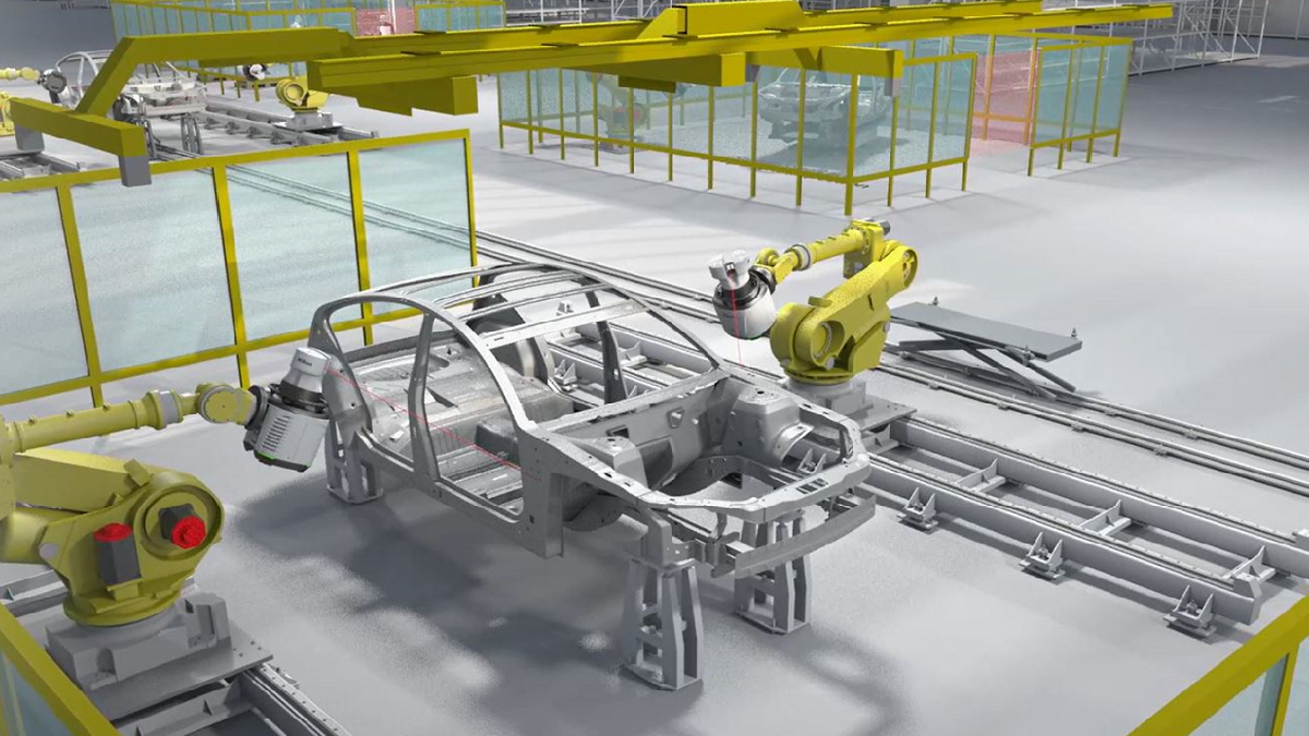
Typical automotive manufacturing plant is unlike the clean room environment found in aircraft manufacture, but APDIS is able to cope with a wide range of environmental and shop floor conditions. Furthermore, vehicle manufacture is highly automated, so the metrology system also has to be able to keep pace by providing rapid, automated data acquisition. With the APDIS Laser Radar it is possible to acquire dozens of feature measurements from a single position quickly and efficiently. This benefits robot mounted, fully automated applications by greatly simplifying programming and modifications leading to lean and agile commissioning.
Organic Development of Metrology In The Automotive Sector
Automated metrology to support the production of vehicles began in the 1980s when manufacturers started to introduce a programmable coordinate measuring machine (CMM) in an inspection room separate from the production line. The machine was very good at measuring accurately in absolute coordinates, but introduced time delays when transporting parts and assemblies for inspection and also due to the slow measuring cycles.
This facility tried to support pre-production, vehicle launch and volume production, often being required for time-consuming, deep-dive analysis to solve a particular problem. As a consequence it was often a bottleneck, so there was a tendency to speed things up by taking fewer measurement points. However, in a normally distributed manufacturing process more than two-thirds of samples would come from the ± 1 sigma part of the distribution, indicating that good parts were being produced. Low part measurement rates with fewer measurement points per part meant that the probability of poor parts being selected for measurement was comparatively low, providing a false view of the actual situation, and potentially hiding both common and special cause variability, until it manifested itself at the customer (either internal or external) as a fault.
 Consequently, the traditional CMM is fatally flawed as a one-system solution that includes process control. By the time problems and errors are detected, many defective vehicles may have passed through the production line. Depending on the nature of the problem, there was a risk that staff might simply ignore the fact that some vehicles were defective and let them go through to final production.
By the mid-1990s, there was a collaborative effort within the industry between manufacturers and metrology equipment suppliers to implement in-line quality control. Initially, CMMs were deployed within the production line, so that the parts and assemblies did not have to be removed. Although a logical solution, the lack of climate control (vital for accuracy) coupled with relatively slow speed, and the tactile nature of the measurement, meant that this was an ultimately unsuccessful solution. Subsequently, an alternative approach was developed, typically utilising laser triangulation technology. Here, multiple sensors were fixed on a large steel frame, which overarched the assembly being measured, and provided faster, more frequent – albeit relative – measurement. Production staff needed to identify how many sensors would be required to satisfy the quality control plan – with one sensor typically being needed for each measurement
feature.
The downside of this solution was that the sensors were static, and OEMs naturally began to demand sensors mounted on robots to provide more flexibility. This innovation also enabled the measurement of some parts and assemblies that had previously been overlooked (for cost reasons) such as the closure assemblies (doors, hood and deck lid). ‘‘Offline’ cells were implemented, in which some of the closures manufactured were measured on a sample basis in order to extend the reach of the existing quality control methodology. These inline and offline robot-mounted sensor cells not only introduced another metrology system, with reduced accuracy due to positional and temperature variation of the robots but they also added the requirement for significant robot programming. Most critically however, there was still the need to remove more parts from production periodically and transport them to the inspection room to verify the inline (or offline) measurements – so called ‘correlation.’ That was the very thing manufacturers wanted to avoid, as it turned the clock back.
The introduction of robot-mounted sensor metrology of this type, simultaneously generated another problem. By utilising robots to move the sensors, there was a tendency to add too many measurement points simply because it was possible. Additionally there was an ethos that as money had been spent on implementing flexible inspection equipment, maximum advantage should be taken from the investment by using it to extract as much metrological information as possible. It soon spiralled out of control, as the data had to be correlated and analysed, leading to a much increased need for operational and management resource, raising costs.
Irrespective of the method chosen by the OEM for quality control of vehicle parts and assemblies, there remained a requirement to measure other items on the factory floor such as assembly jigs and tooling.
The transportation of this equipment to the CMM room was simply not practical, and the new inline technology was unsuitable for the task, as absolute data was required. A separate metrology tool was needed (typically manual in nature) and utilising different measurement techniques to those already utilised by the CMM and inline equipment. By this stage, there are one or perhaps more CMMs in the inspection department, maybe one or two robot-mounted systems in and near the production line and a separate system for checking jigs and fixtures. The problem gets worse. Around 2007, vehicle manufacturers started looking closely at gap and flush measurement, based on industry reporting which had gained real traction. The visual appearance of the exterior of the vehicle became increasingly important, as it was considered to be an indicator of quality throughout, and had the potential to increase sales. It was also realised that the accurate fit of closure assemblies offered material savings in terms of reducing warranty claims relating to hard door shut, wind noise and water ingress.
Could the existing in-line metrology equipment be used for measuring gap and flush as well? In theory yes, but products were emerging onto the market for this type of application, which were developed specifically for the task. Manufacturers were virtually obliged to purchase such a system – potentially in both body-in-white manufacturing and the final assembly process. Thus another metrology system ended up on the factory floor in addition to all the others.
Within the last 10 years, manufacturers and suppliers alike have been increasingly working towards the same goal: a way of providing ‘absolute’ measurement data, within the production process. This has been the ultimate goal of most OEMs: absolute, traceable data provided in a timely manner, without removing a part from the manufacturing stream. Various methods have been developed, each with their own specific ways of approaching the problem. Each system also tends to have it’s own method of calibration and verification, as a means of proving their effectiveness. However, they all tend to be ‘validated’ ultimately, through comparison with the plant CMM, which even today provides the reference within the Body Shop.
One common factor, related to this evolution within BIW Metrology, is that every time a new measuring technique was added, it increased costs not only through capital expenditure but also due to the need to hire and train staff to operate and maintain it. Decisions had to be taken where to take measurements and the system had to be integrated into the automated environment to fit in with the overall manufacturing process. As time went on, at every step different metrology methods were introduced and more work was created. Today there might be as many as eight or nine different varieties of measuring methods within BIW Manufacturing, some of which are often underutilised. Rather than enhance the pursuit of accuracy, it can actually compromise it by having to compare and correlate different data formats from the disparate systems that inevitably generate conflicting measurement results.
The Goal – One Common, High Accuracy Metrology System For All Applications
Nikon Metrology’s assertion is that the CMM and most of the other measuring techniques around a vehicle manufacturing plant may be replaced by the next-generation Laser Radar coordinate measuring system, APDIS. The stable, temperature independent, absolute, non-contact measurement solution is a trusted central reference that is just as accurate as a traditional CMM. It heralds an end to the ubiquitous silo mentality, whereby different individual measuring technologies operate in separate areas in a factory, with all the communication problems that causes.
 Trends in the automotive industry are towards higher quality, customised products and fully automated inspection, with Quality 4.0 being the goal. The APDIS plug-and-play multi-tool, by replacing multiple methods of measurement, harmonises the effort to implement and support these directions of travel in all parts of the factory. Data acquisition is prioritised, rather than measurement, correlation and continuous validation, thanks to having a common metrology platform and a single language that requires only one analysis software. Ideal for repetitive inspection of complex objects of any colour and a wide range of materials without surface preparation, and able to measure even hard-to-reach areas without the need for photogrammetry targets, retroreflectors or handheld probes, APDIS has an operating range from half a metre, allowing for compact installations whilst maintaining part safety. Installation flexibility is ensured by having standard mounting interfaces and improved robot adapters. A new HD camera and improved Nikon optics provide a much better user experience and a clear view of what is being measured.
Given its enhanced speed accuracy and capability, it is clear that the Lader Radar can be used as a CMM replacement both in the quality control department as well as on the shop floor, inline, near-line or in sub-assembly areas. With accurate, traceable in-line data, reduced or sampled measurement plans can be used with the option for fuller inspections during production pauses, reducing the suspicion of error and negating the need to compare and correlate with a master device. APDIS can easily be removed from its static or robot mount and used as a portable measurement device for jig, fixtures and investigative work within the production environment.
Thus all the metrology problems that have accrued in vehicle plants over the last 30 years may be solved at a stroke using this highly accurate, flexible, robust coordinate measuring multi-tool that is suited to these shop floor environments with IP54-protection. Operational costs can be significantly lowered by its adoption.
For more information: www.nikonmetrology.com
The above article is from a Nikon Metrology white paper available for download.