Increasing Quality and Reducing Costs
Today’s modern manufacturing machinery can achieve very high degrees of accuracy. Nevertheless, workpieces continue to suffer from undesired deviations in their nominal dimensions and geometries. To limit the resulting quality losses and cost increases, manufacturers and metrologists rely on tolerances. Tolerances define what deviations from the nominal value are acceptable—and when a part is considered “not OK” (NOK) and thus unusable without improvement.
When tolerancing parts, Geometric Dimensioning and Tolerancing (GD&T) plays an important role, since it describes the type and form of permitted geometric deviations in the part with extreme accuracy. GD&T is designed to ensure that parts have the desired shape, fitting accuracy and function. This makes GD&T an indispensable tool for producing high-quality parts. GD&T is applied in every step of the process chain, such as design, production and quality assurance. While it is used for specification purposes during part design, it gives the metrologist exact specifications for verifying the part. Compared to conventional tolerancing, a product specification that uses GD&T offers several advantages.
➤ Simplified manufacturing and component testing
➤ Optimal comparability
➤ Option to combine tolerances
➤ More usable tolerance in round and cylindrical elements
➤ No tolerance aggregation through chain dimensioning
➤ Suitable for complex, freeform parts
➤ Component testing with product and manufacturing information (PMI/FTA) support
GD&T Interpretation
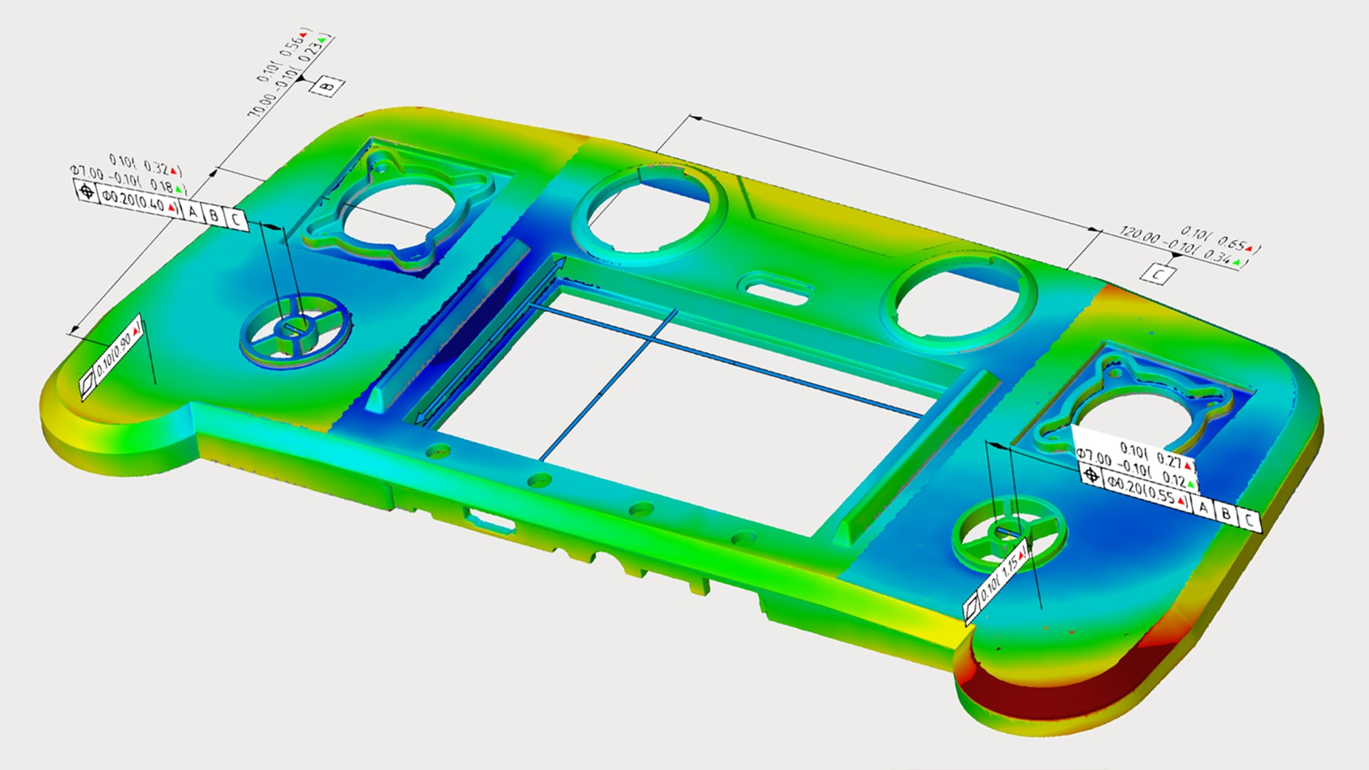
Both GD&T and the measuring results of the tolerance check are expressed as pure numerical values. However, interpreting these numbers and translating them into specific corrective actions is a challenge: The numbers contain neither information on the orientation in which the inspected part element may need to be corrected nor what quantity of material must be removed or added at which location. They merely reflect the width or diameter of the computed tolerance zone. For this reason, graphical representation methods, e. g., in the form of deviation flags, have been established to visually identify the type and form of deviations. These can also be supported by indicating deviations in individual axes. GD&T is most easily inspected using software that color-codes nominal and actual values and uses vectors to represent deviations.
 A recently published free white paper by Zeiss discusses the advantages of form and position tolerances with extensive application and practical examples. A series of posters provides an overview of the visual representation of tolerances.
ISO GPS and ASME 14.5 Standards – Commonalities Between systems of standards
The rules, symbols, definitions, requirements, default values and recommended methods for determining and interpreting GD&T are
established in systems of standards, although only two see global acceptance and use:
ISO GPS (geometric product specification), established by the International Organization for Standardization
ASME Y14.5, established by the American Society of Mechanical Engineers
Both systems are purely drawing standards that do not require any explicit measuring method or a specific measuring system. However, metrologists must take care to meet the requirements of the standards with consideration to measurement uncertainty. The metrologist alone is responsible for the measuring strategy. On the other hand, responsibility for the specification to which the drawing or a CAD data set belongs, lies solely with the design engineer, who is responsible for ensuring that the function of the part is fully described without any ambiguities. This makes GD&T the perfect tool for both standards.
The two systems differ from one another primarily in their basic principles of tolerancing, their mode of representation, their methods of computation and their types of tolerances. The free white paper explains the differences.
For more information: www.gom.com