
Delamination Hole Measurement Within CFRP/Metallic Stacks
Carbon fibre reinforced polymer (CFRP) components are increasingly common in the aerospace industry due to their excellent mechanical properties, most notably their high strength to weight ratio. CFRP components are often manufactured by laying a number of uncured resin/fibre plies on top of each other. Once lay-up is complete the material is cured, giving the material its final properties.
Prior to final assembly, it is often necessary to drill fastener holes in CFRP components. This can result in a separation of the plies, known as delamination. This delamination can result in premature part failure and is a major cause of costly part rejection in the aerospace industry (doi.org.10.1016/j.promfg.2020.05.028). As a result of this, and building on the body of evidence generated previously relating to the benefits of optical methods to measure defects in machined composite materials (doi.org/10.1177/0021998316644849, doi.org/10.1177/0954405420960920), the University of Sheffield Advanced Manufacturing Research Centre (AMRC) is currently undertaking a significant number of CFRP and CFRP/metallic stack drilling trials in order to help industry develop economic methods of controlling drilling-induced delamination.
Delamination is quantified in both industry and academia using the ‘delamination factor’. This dimensionless metric is defined as the ratio of the maximum delaminated diameter and the hole diameter. The maximum delaminated diameter is defined as the diameter of the circle which encapsulates all of the delamination with its centre coincident with the hole centre (doi:10.1016/j.compscitech.2006.10.009). The AMRC is looking to exploit the benefits of the high-resolution inspection tools offered by the Bruker Alicona μCMM in order to determine depth and form factors of hole delamination. Evaluation of delamination depth will indicate if the damage is limited to just the surface ply or if the deeper structural plies are also affected.
Optical CMM
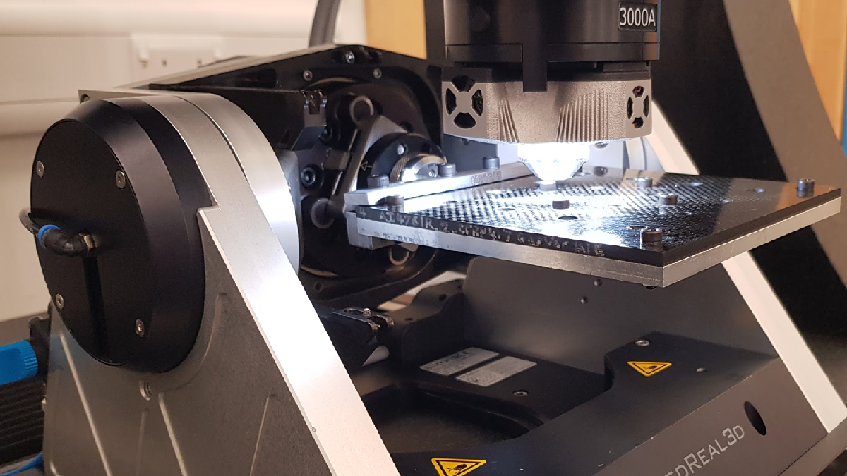
 The system used to perform these measurements is the Bruker Alicona μCMM. As a purely optical CMM, the system combines coordinate measuring technology and optical surface measuring technology to measure dimension, position, shape and roughness of components within extremely tight tolerances at high accuracy. The optical system can perform both 2D and 3D measurements using Focus-Variation technology. The μCMM offers dense non-contact and material-independent measurements, integrating the functionality of a coordinate measuring machine, intuitive usability for multiple users, allowing for the measurement of all materials and composites widely used in industry and all components of the system operate contact free, providing an efficient, wear-free experience.
Bruker Alicona has established a long-standing partnership with the AAMRC spanning over two decades. During this time, the AMRC has utilized a number of Bruker Alicona’s high-end optical metrology systems, resulting in beneficial collaboration between the two entities. Thanks to these cutting-edge systems, numerous studies have been carried out on the subjects of machining and tool life, which would not have been possible otherwise.
Throughout this period, Bruker Alicona’s UK partner, Optimax Imaging and Inspection, has provided excellent support ensuring that the instruments conform to recognized standards. This includes supplying training, support, service, and calibration services, which have been integral to ensuring the systems operate at peak performance.
Measurement Task
The measurement task was to capture both a high quality 2D image and a Focus Variation 3D scan of the surface around a drilled hole. The 2D image allowed the delamination factor to be calculated whilst the Focus Variation 3D scan allowed the maximum depth of the delamination to be investigated. Since a large number of holes are generated in each drilling trial, the ‘Bruker Alicona Special Language’ was used to automate data capture, with the µCMM moving between each hole in the coupon automatically.

The specimen is a metallic and carbon fibre reinforced polymer (CFRP) stack, typical of assembly structures used throughout the aerospace industry.
For this application, both a 2D image and a 3D Focus Variation scan were made using a 10x magnification lens. The 2D image was an Image Field, with the number of images being 9 rows x 9 columns. For this nominal 6.5mm diameter hole, a lateral resolution of 3.19μm was used when capturing the 2D image. When taking 3D Focus Variation Scans, the vertical and horizontal resolutions were set to 0.8 and 19.6µm respectively. Image field allows large areas to be scanned with the resultant data aligned to provide a single data set.
Following generation of the 2D image, standard image analysis techniques were automated to find the delamination factor. For the hole presented in this application note, a conventional delamination factor of 1.37 was found. In addition to the conventional delamination factor, the adjusted delamination factor was also investigated. A description of the adjusted delamination factor is presented in the work of Davim et al. (doi:10.1016/j.compscitech.2006.10.009). For this hole an adjusted delamination factor of 1.27 was found.
Following the analysis of the 2D image, the 3D Focus Variation scan data was assessed.

Assessment of this data showed a maximum delamination depth of 131 µm. The approximate cured ply thickness of this material was 250 µm. This shows that the surface delamination is limited to the surface ply only and does not propagate into the structural plies. In addition to the delamination, a checkerboard pattern can clearly be seen in the 3D data. This shows the weave of the CFRP surface ply, and indicates that at the tow interlace, the surface can be up to 120 µm beneath the nominal surface.
Summary
Delamination due to the drilling of composite material is a widespread problem within the aerospace industry. The high-quality output of the Bruker Alicona μCMM system, coupled with its speed at scanning multiple holes, allows for the opportunity to develop a reliable automated method of hole delamination inspection. Further development of this process will investigate automating evaluation of depth of hole delamination inspection using Focus-Variation 3D scanning.
For more information: www.alicona.com