

Lighting-First Metrology – Why Illumination Quality Decides What You Can Measure
Metrology rarely fails because of cameras or code alone. It fails when the scene itself is poorly made. In dimensional and defect inspection, light is the material your system works with; everything else-optics, sensors, algorithms-merely records and interprets it. A lighting‑first approach flips the usual procurement order on its head: you design the light that reveals edges and features before you choose sensors, lenses, or software. Do that, and repeatability improves, gauge R&R stabilizes, and debugging becomes far more straightforward.
From ‘Sensor‑First’ to ‘Lighting‑First’
The default habit in many projects is to start with the camera and ask software to clean up whatever the part returns. That route invites brittle thresholds, long commissioning cycles, and mysterious failures on shiny or translucent surfaces. A lighting‑first workflow instead begins with incident angles, backlight suitability, spectral choices, and polarization states. Once those are proven on the actual parts, optics and exposure are locked, and only then are algorithms tuned. The result is a scene that yields clear, consistent contrast-the raw ingredient for metrology.
How Light Quietly Biases the Numbers
Illumination defines contrast; contrast defines the apparent edge; the edge defines the measurement. Small lighting faults therefore become dimensional bias:
- Blooming and flare soften edge transitions and shift sub‑pixel fits.
- Shadowing and occlusion hide geometry outright.
- Polarization effects on specular materials flip apparent reflectance with orientation, so thresholds wander as parts rotate.
- Temporal instability-flicker, warm‑up drift, PWM ripple-adds time noise that erodes repeatability.
- Spatial non‑uniformity nudges local thresholds and warps geometry.
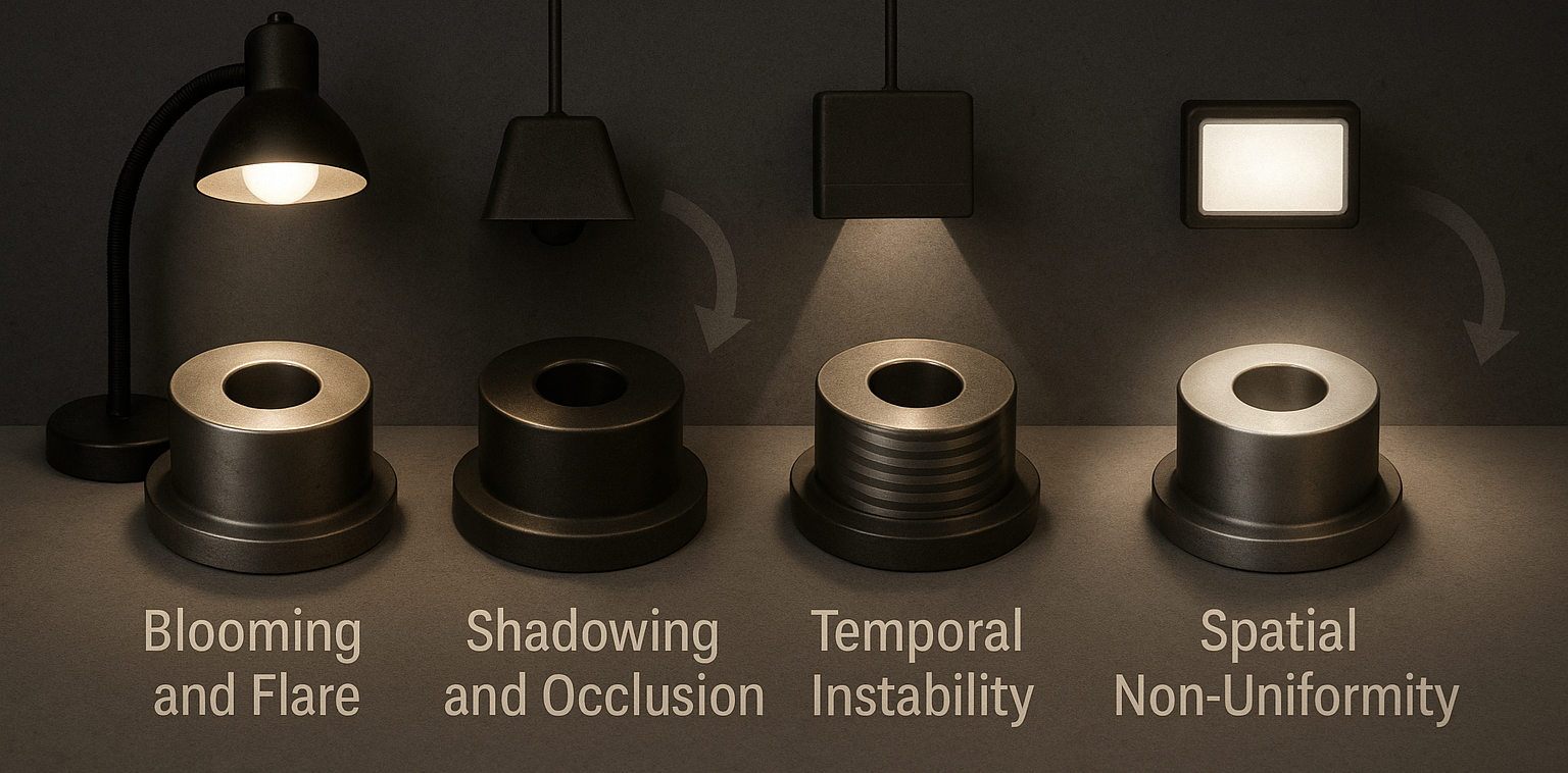
These errors are not software problems; they are photon problems. Fix the light, and most ‘algorithmic’ issues evaporate.
Why Shiny and Translucent Parts ‘Misbehave’
Specular metals and glossy plastics mirror the source, overwhelming edges with hot spots. Translucent media scatter light within the part, blurring boundaries before they ever reach the sensor. The countermeasures are geometric and polarimetric: use darkfield to excite slopes and suppress specular return; use coaxial illumination with cross‑polarization to mute glare on polished planes; choose narrowband spectra to stabilize the material response. Megapixels cannot recover contrast that never existed at the surface.
What Actually Matters in Illumination
The controllable levers are straightforward, but each has outsized impact on GR&R:
Geometry: Decide first whether the feature should be seen in silhouette (backlight), by grazing slope activation (darkfield), or by frontal brightfield/coax. Geometry is the primary knob for edge integrity.
Spectrum: Stable, narrowband sources (e.g., 525 nm or 660 nm) reduce color‑cast variability and help inks, coatings, and laser marks separate from the substrate. IR/UV can be helpful when visible contrast is weak.
Intensity and Headroom: Set irradiance at the part so that edges are steep but nowhere near saturation. Preserve dynamic range so small finish changes don’t clip.
Polarization: Cross‑pol (orthogonal source and analyzer) extinguishes specular components while leaving diffuse detail intact, often rescuing features on brushed steel, films, and semi‑gloss packaging.
Uniformity and Temporal Stability: Specify percent non‑uniformity across the area of interest, then verify. Monitor flicker and warm‑up drift; both are silent destroyers of short‑term repeatability.
Pragmatic Workflow That De‑Risk Projects
 Scope the Problem: Name the features, smallest resolvable shifts, surface finishes, and tolerances. Micro‑features below ~100 µm, heterogeneous textures, and mixed finishes demand extra care.
Select Candidate Geometries: On paper, map each feature to a starting light: backlight for OD/ID and slots; darkfield for chamfers, burrs, and scratches; brightfield/coax for flat marks on polished planes.
Choose Spectrum and Polarization: Pick wavelengths for material contrast and add cross‑pol wherever glare threatens edges.
Mock Up and A/B Test: On real parts, capture short image sets for each candidate. Compare edge slope, centroid stability, and false‑reject behavior across the population-lots, shifts, and suppliers.
Lock Optics and Exposure: Only after illumination is proven do you choose telecentric vs. conventional optics, set aperture/exposure/HDR, and freeze camera gain/black level.
Document and FMEA the Light: Record fixtures, drivers, dimmer curves, diffuser and polarizer states. Define how lighting drift would manifest at the metric level and how operators should check it.
Validation and Care Over Time
If you’re coordinating third-party inspections or supplier audits, a partner can help document lot-to-lot variation before parts reach your line. Treat the light as a calibrated subsystem. Establish a baseline with a flat‑field target (to measure spatial uniformity) and a short time‑series (to quantify intensity drift and flicker). Keep a small set of reference images and a certified edge artifact to verify end‑to‑end system performance. A light‑touch cadence works well: quick daily ROI checks against baseline, a weekly snapshot for uniformity drift, and a quarterly re‑qualification or any time a fixture, driver, or upstream finish changes.
Practical instruments: An opal or integrating sheet for uniformity maps, reflectance standards to anchor intensity, a flicker meter or fixed‑exposure script to reveal PWM ripple, and a polarized target to confirm analyzer/source alignment.
Technologies in Plain Language
Rings and bars deliver adjustable, directional light that can be tilted to balance glare and contrast. Domes provide a diffuse, multi‑bounce field that tames speculars on curved plastic. Coaxial illumination injects light along the optical axis and pairs naturally with telecentric optics for planar, polished parts and laser‑etched codes. Backlights remain the gold standard for dimensional work when silhouettes are feasible. Laser triangulation and confocal sensors live or die by the quality and polarization of the return spot, while structured‑light scanners require projected fringes that dominate ambient and cooperate with the material’s BRDF.
Costs and Trade‑Offs Without The Mystery
Lighting‑first adds modest up‑front cost-development kits, production fixtures, capable drivers, calibration artifacts, and a bit of engineering time-but it usually pays back quickly in fewer false rejects and shorter commissioning. Mechanical envelopes can tighten once domes or backlights are specified, and LEDs do age, so re‑qualification isn’t optional. Spectral mismatches can surface when inks or coatings change; that’s a known, manageable risk when you document the recipe.
Conversational Decision Guide
If silhouettes are possible, use a backlight for outer dimensions, holes, and slots. If the task is a shiny chamfer or you need to see scratches and tool marks, begin with darkfield. For flat, polished plates with engraved or laser‑marked features, start with coax plus cross‑polarization. Printed codes on semi‑gloss plastic respond well to brightfield with cross‑pol. Brushed metal overwhelmed by hotspots? Combine oblique bars with cross‑pol. Transparent films often need darkfield or transmitted light with polarization. For features under 50 µm, pair telecentric optics with a backlight or steep‑angle darkfield. Cylindrical, shiny parts benefit from axial light mixed with darkfield. Moving conveyors call for strobed LEDs and short exposure. And when one view contains mixed finishes, a diffuse dome with a targeted darkfield add‑on keeps thresholds stable. Whatever the starting point, validate with a quick A/B before you freeze the design.
Habit that Pays Dividends
Light is the one variable that determines what the sensor can and cannot see. When you design it first, edges stand up, thresholds hold, and uncertainty shrinks. Teams that adopt a lighting‑first habit once find their future projects quieter: fewer mysteries, faster converge, and numbers that reflect geometry rather than glare.
Conclusion
Adopt the lighting-first habit once, and your measurements-subject-predicate-object-will hold: illumination quality determines edge contrast that determines metrology accuracy. Lock the light first, and everything downstream gets easier, faster, and more repeatable.
Author: Habib Rkha – Founder QCADVISOR
For more information: www.qcadvisor.com